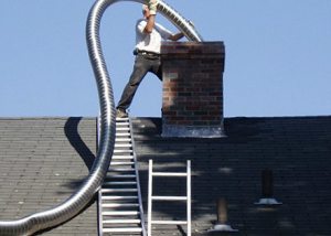
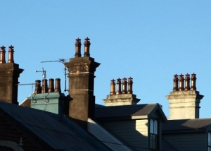
Deflector for ventilation - an aerodynamic device installed on top of the ventilation duct (pipe) of the supply and exhaust system, the device improves the efficiency of air exchange. This happens both due to the enhancement of natural traction, and because it prevents the entry of wind gusts into the channel and all that can be carried by them or fall on their own.

Ventilation systems are often equipped with deflectors, such devices contribute to increased traction
Content
What is the device and the principle of operation of the deflector on the ventilation pipe
Considering what a deflector in ventilation is, we see that the device is composed of the following unchanged components:
- two glasses of cylindrical shape. The inner cup is flat, the outer cylinder has an expanded lower part. In the upper part there are hangings in the form of rings, with the help of which the direction of the air flow is changed. Installation of rebounds is carried out so that a negative pressure is created by the wind flow, which contributes to the accelerated drawing of gases from the ventilation channel through the space between the rings. A lid is fixed above the upper glass, which can be shaped like an umbrella that redirects wind flows;
- brackets for the cover;
- branch pipe.
The ordinary scheme of the ventilation deflector is a kit consisting of:
- a diffuser that slows down the atmospheric air flow and increases the pressure in the ventilation duct. The lower part of the truncated cone is mounted on top of the ventilation duct;
- an umbrella attached to the diffuser with legs. The presence of the upper protective cap prevents dust, leaves and other debris from entering the cavity of the channel;
- housing (rings or shells) connected to the diffuser using two to three brackets. The plane of the body dissects the wind flow, which contributes to the formation of the area with reduced pressure inside the cylinder.
Note! A grid is attached to some models to delay small debris, but this adversely affects the level of traction, albeit slightly.
A deflector mounted on the ventilation pipe acts in this way. Encountered on the body of the wind flow is dissected by a diffuser. This leads to a decrease in pressure in the cylinder and, accordingly, to increased traction in the ventilation duct. The deflector installed in the exhaust ventilation, the more efficiently it enhances the draft in the air ducts, the greater the resistance to the wind flow path created by the body of the device.

A net is attached to the deflectors to protect the pipe from debris, but this can affect traction
When the wind flow rushes to the ventilation deflector from above, the outflow of exhaust air goes from below. With a wind flow rushing from the side, outflow occurs simultaneously in two directions, upper and lower. The mechanism of an air deflector mounted on a ventilation duct pipe works in the worst way when the air flow is from below, from the roof, preventing the gases discharged through the upper opening.This disadvantage inherent in all types of devices has to be reckoned with. To attenuate the negative impact of the wind flowing from below, the lid is given a special shape, which is two cones connected by bases.
With the correct installation of the deflector, an increase in the efficiency of the ventilation system can reach 20%. This is determined by the influence of several factors:
- installation height relative to the roof level;
- device dimensions;
- its form;
- slight slope of the ventilation pipe (at least, as is commonly believed).
Varieties of ventilation deflectors
The purpose of all considered devices is the same:
- contribute to increased natural traction to improve air exchange in the building;
- prevent atmospheric precipitation, dust, leaves and other debris from entering the system;
- prevent the penetration of insects and small birds.
As for manufacturing, the range of devices is extremely diverse, and the differences are noticeable even visually.
As a material for the manufacture of use:
- copper. However, it is extremely rare, due to its high cost;
- aluminum;
- ceramics;
- galvanized steel;
- stainless steel;
- plastic. The plastic ventilation vent has several advantages in the form of low cost and decorative capabilities created by the choice of shape and color. But the effect of high temperatures significantly affects the operating life.

For the manufacture of deflectors, stainless steel is most often used, it is durable, relatively inexpensive and not subject to corrosion
Good to know! The strength inherent in metal in some models is combined with the decorative capabilities of polymers by putting a plastic cover on a metal (aluminum or steel) base.
According to the principle of operation of the device can be:
- static. These are the simplest designs that can well be assembled independently;
- static with an ejector fan. Under the fixed hood, a low-pressure axial fan is installed, which rotates only if the pressure of the wind flow or thermal has decreased. The inclusion occurs when the sensor is triggered and leads to normalization of traction to a natural level;
- rotational. The rotary deflector is equipped with a paddle drum. The rotational ventilation deflector has a static base and a movable head, the rotation of which is provided in one direction, which does not change when the direction and strength of the wind flow change. The rotating head creates a vacuum in the ventilation duct, which prevents reverse draft. Rotary devices are characterized by productivity that is two to four times higher than the capabilities of static ones. They prevent condensation in the roof during the summer heat, as they help lower the temperature in the rooms, reducing the cost of using the air conditioner;
- with ejector and swivel housing. A rotating deflector is placed above the ventilation duct. The design of the rotating device is composed of two pipes arranged vertically and horizontally, for the connection of which a hinge mechanism is used, and a partition acting as a weather vane is installed on top.
By design features, device models are classified as closed or open.
In form they are:
- square;
- round.

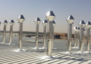
Deflectors are available in different forms, you can choose a model for any pipe section
An umbrella can be one or more.
As a rule, choosing a model of a ventilation deflector taking into account climatic features, rarefaction coefficients and local losses and taking into account the cost, they stop at one of the most common designs:
- Volperta.
- Grigorovich.The most popular design available for making by yourself and consisting of three main elements: 1 - a diffuser, 2 - a protective umbrella, 3 - a reverse hood;
- double.
- H-shaped. It is customary to install at industrial facilities, since the design maintains the system's operability in case of sharp gusts of wind and is able to use air flows going from the bottom up. The wind stream entering the vertical lintels extends the working medium, which entered the horizontal channel, which leads to an increase in natural draft;
- weather vane baffle. The “hood” or “net” is assisted by a weather vane oriented along the wind flow. Air passing through curved visors changes direction, rushing upwards, where a region of deep rarefaction is formed.
- TsAGI. The design developed at the Aerohydrodynamic Institute is distinguished by the possibility of choosing the type of connection to the duct (retaining, nipple, rack, flange), based on the shape of the neck of the ventilation shaft. The disadvantages include the tendency to form an ice blocking passage and drag resistance in the absence of wind;
- spherical.
How to make and install a ventilation deflector yourself
Self-made manufacturing of a rotating ventilation deflector, as a rule, is not recommended due to the significant complexity of the design. But with the Grigorovich deflector it is quite possible to tinker independently, since with the simplicity of the device it guarantees the uninterrupted operation of the ventilation system.

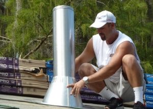
You can assemble and install a simple model of the deflector yourself
Drawing a diagram and drawing up calculations are based on the parameter of the diameter of the ventilation shaft. Based on this indicator, it is customary to take the following coefficients:
- 1 - for the inlet pipe;
- 1.7 - for the height of the diffuser;
- 1.3 - for its width;
- 1.8 - for the width of the protective cap.
To begin with, it is worth making cardboard patterns for all the elements, then to attach them to a metal sheet and cut it out. But self-confident workers can afford to neglect this stage, transferring all the development patterns of structural elements onto a metal sheet.
Having cut out all the necessary elements with the help of metal scissors or grinders, they proceed to their assembly, using welding, bolts, rivets or self-tapping screws for this purpose. It is preferable to use bolts or rivets, since working with a welding machine for thin sheet metal requires decent qualifications.
The sequence is as follows:
- Going to the diffuser.
- Brackets are attached to it that will hold the umbrella.
- The protective cap is mounted.
- Brackets are attached to the inlet pipe.
- The upper part of the brackets is connected to the diffuser.
The installation is subject to the norms of SNiP; during its implementation, the following rules are followed:
- when installing a circular deflector on a square pipe, use a transition pipe;
- the trunk of the ventilation duct is equal in height to the chimney so that smoky air does not penetrate into the premises of the building;
- installation is not allowed if the device falls into the aerodynamic shadow formed by neighboring buildings;
- placement should be made so that the deflector is freely blown by wind currents, it is best if it becomes the highest point of the roof;
- when mounting on a flat roof, the minimum height is from 500 mm;
- with the distance of the ventilation duct from the roof top to a distance of one and a half meters, the deflector rises above the roof ridge (parapet) by at least 500 mm;
- with a distance between the air outlet and the roof parapet of one and a half to three meters, the deflector should be no lower than the level of the roof ridge;
- at a distance of more than three meters, the virtual line drawn between the ridge and the protective cap should not deviate by more than 10º.
Important! Installation of the deflector requires compliance with these rules, otherwise its effectiveness will be inadequate.
By installing a deflector on the supply and exhaust ventilation pipe, it is possible to achieve a number of advantages that provide a higher level of comfort when using the premises. Simpler models may well be made with your own hands and turned into design elements of the exterior of a private house. The main thing here is not to forget about the requirements of SNiP and design features of the deflector model related to operating conditions.